Visual Design and Engineering Laboratory
Carnegie Mellon University
Sketch-Based Modeling System
Executable
Executable
You may find the windows executable here.
Tutorial
Here a tutorial is given for an experimental sketch-based subdivision modeling program. Please see the above video for a quick demonstration. The introduced approach is based on the use of sketch-based interfaces for design of subdivision surfaces through curve-based interactions. One advantage of this approach is that, it allows a two way interaction between the designed curves and the underlying surfaces that enables rapid design of smooth surfaces with typical design features. The car design below shows an example model (Hover your mouse to see the curve network structure).
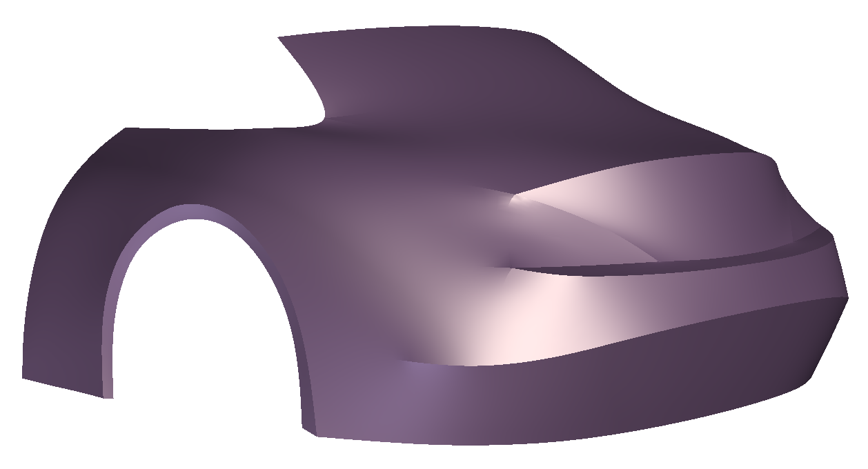
A car example. Hover mouse over to see the underlying curve network.
The main body of the work has been presented in the SBIM 2011, Vancouver. For a more detailed description of the innerworkings, please see the project page.
Curve Design
Curve design is at the heart of the interactions as it allows quick initiation, development and modification of a curve network that serves as a wireframe for an underlying surface.
Symmetric sketching

This tool allows the user to quickly create symmetric pairs of curves in 3D space about a prescribed symmetry plane (Figure 1 shows the symmetric plane by green-blue colors). For symmetric designs, the majority of the curves required by the design may be created solely by this tool, although there are alternative ways of creating curves and controlling symmetry as will be discussed later. As these curves are created symmetrically, they preserve their symmetric properties during modifications, unless specifically removed by the user.
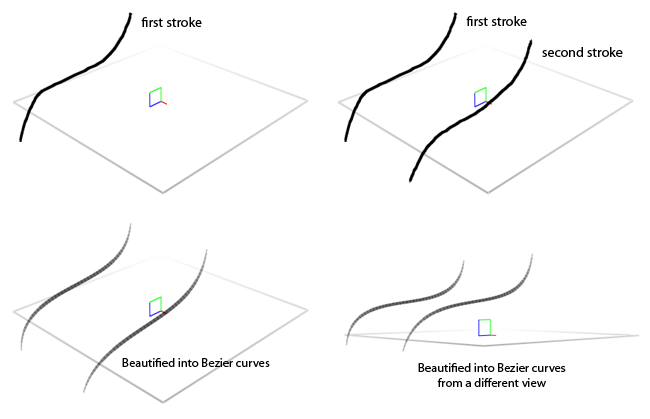
Figure 1. Sketching symmetric pairs of curves.
With this tool selected, draw two curves from a particular viewpoint. Typically 3/4 views should be used for best results (Other viewpoints that are parallel to the three principal axes and planes cause computational instabilities.). For symmetric curves that cross the symmetry plane, draw the curve and hit ‘Enter’.
Created curves can be deleted at any time, by first selecting them and then pressing ‘Delete’.
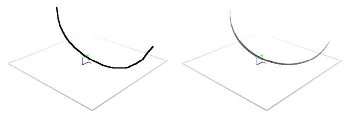
Figure 2. Self-symmetric curve is contructed by drawing and hitting ‘Enter’.
Drawing on surface

With this tool, users can draw curves directly on existing surfaces. The stroke drawn on the viewing plane is projected on to the existing surfaces using the depth buffer of the rendering. This tool is particularly useful in creating different curve configurations (thus, curve topologies) that result in surfaces with similar geometries. One common use of modifying the curve configurations is adding characteristic feature curves that will later be used to control how surface patches transition from one to another.
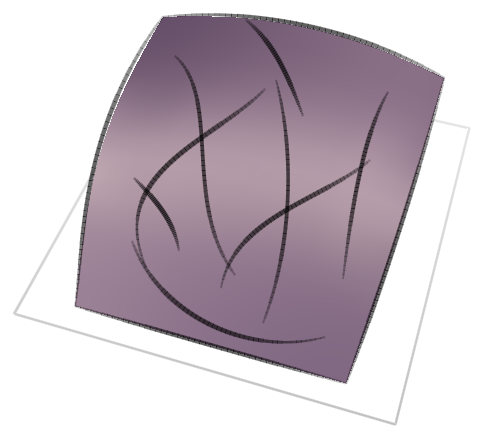
Figure 3. Drawing on existing surfaces.
Trimming and joints

This tool is essential in defining closed loops of curves. These curve loops constitute candidate patch boundaries which will be automatically detected and surfaced. The joints defined by this tool are preserved during modifications. If one curve at a joint is modified, the others are also modified minimally to preserve the joint structure.
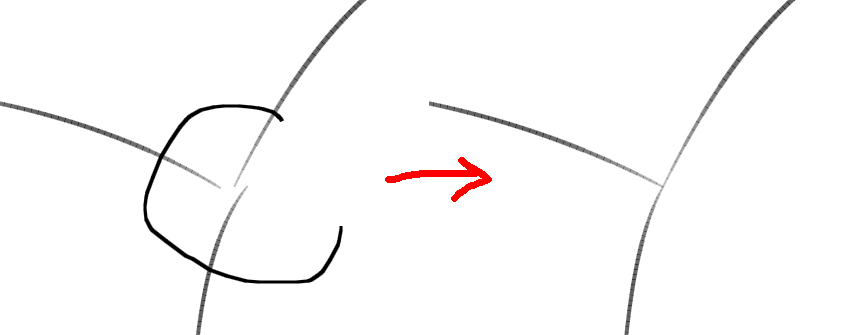
Figure 4. Joining curve ends together.
Curve modification tool

This tool enables modifications of 3D space curves using 2D strokes. Users can modify the projections of a curve, or a series of connected curves from a user-defined viewpoint. Typically, to properly adjust the shape of a 3D curve, at least two modifications from two different viewports is required. This tool is the most frequently used tool during shape exploration as users iteratively try different configurations and resulting surfaces throughout the process.
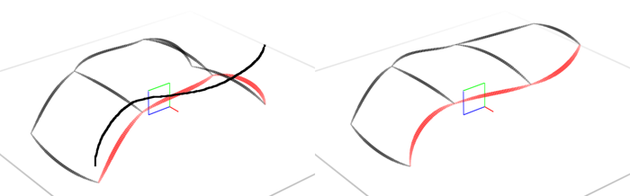
Figure 5.Modifying curves.
Curve extensions

This tool enables quick extensions to be made to a curve or a series of curves. From a particular viewport, the user draws the final positions of curves similar to using the modify tool. A new curve is created at the calculated final position and is connected with the original curve to define a four sided patch. This tool is particularly useful in quickly developing the curve network where symmetric sketching is not desirable and there exists no previously defined surfaces to draw on.
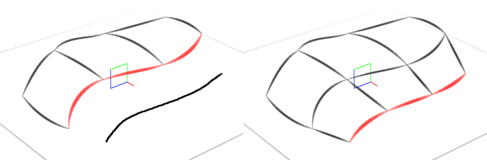
Figure 6.Extending curves allows quick development of the network.
Symmetry control
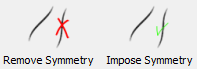
As we have different curve creation methods that can produce both symmetric and asymmetric curves and curve pairs, we also present tools to maintain the curve symmetry. By using these two buttons, existing curve symmetries can be selectively removed. Simply select curves whose symmetric properties are to be removed and click ‘Remove Symmetry’. Similarly, to assign symmetry on a pair of curve, select the two curves and hit ‘Impose Symmetry’. This will not only assign symmetry but it will also modify the geometries such that they are each other’s exact symmetric pair. For curves that are intended to be self symmetric (i.e. crossing the symmetric plane), select the single curve and hit ‘Impose Symmetry’.
Symmetry maintenance is important. During curve modifications, present symmetries are automatically maintained to replicate changes on symmetric curve on its symmetric counterpart. Try to be aware of the automatic maintenance throughout the modeling process.

We also provide a tool to quickly create symmetric copies of asymmetric curves. Typically, extended curves on one side of a symmetric network, can be copied to the other side of the symmetry plane allowing symmetric progression with the extender tool. For this, pick the asymmetric curves and then click on ‘Create Symmetric’.
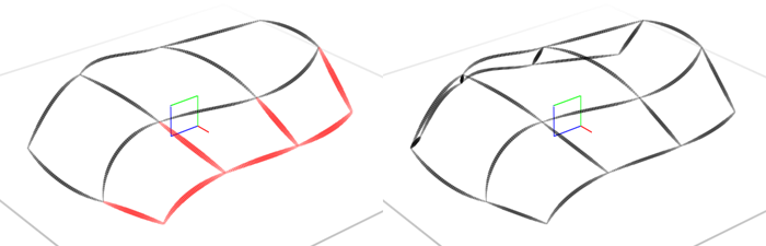
Figure 7.Creating symmetric counterparts of extended regions.
Surface Design
Automatic patching
Once a curve network is designed, the surfaces are automatically identified and patched by hitting the ‘Space’ key. Typically best results are achieved if the curve network has a clear curve loops formed by 3-5 curves. Similar to subdivision modeling, the curve network topology, thus the control mesh topology, directly affects the resulting surface qualities. If some patches do not appear after automatic surfacing, it is either due to missing connections between curves, or the patch is not suitable for the entirety of the network. Please be aware that the code is extremely experimental and might also show glitches during automatic patching.
Similarly, the initial surfaces typically do not interpolate the constituent curves. The surface can be optimized to interpolate the network through iterative updates by pressing the ‘O’ key.
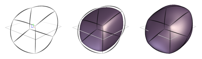
Figure 8.Automatic surface patching and surface optimization for a better interpolation of the curve network.
Surface smoothing
The generated surfaces can be smoothed at any time using the ‘V’ key. An example is shown in Figure
Free, fixed and crease curves: These curve descriptors serve as controllers of the underlying surfaces. All curves are initially defined as free curves that selectively be interpolated by the underlying surface. Fixed curves are interpolated by default. Crease curve, as implied by the term, appear as sharp creases on the surface. Crease curves, by default, act as fixed curves during surface design. During surface design, the user picks where the surface should interpolate the curves and features, and where the surface can be relaxed in order achieve and overall smoothness, and continuous flow of the surface. To assign crease and fixed curves, select the curves you want and click ‘C’ or ‘F’, respectively.
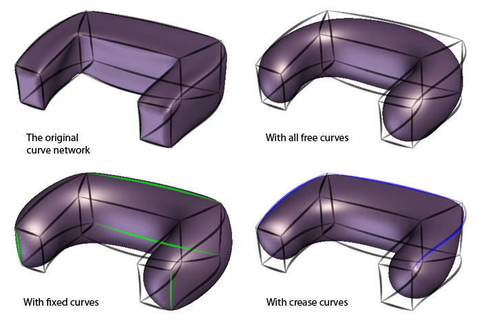
Figure 9.Smoothing the surface with free, fixed and crease curves.
Malleable curve network
After successive surface smoothings, the curve network can be automatically modified to align it with the smooth surface. To do so, the curves that needs to be aligned are selected, and these curves are moved to the associated locations on the surface by hitting the ‘Y’ key. As this process is applied selectively, local modification can be done on the curve network. An example of whole network modification is given in Fig. 10.
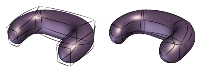
Figure 10.The malleable curve network adjusts itself to the smoothed surface. Although the whole network is modified here, such adjustments can be made locally by selecting a subset of curves.
Keyboard shortcuts
Enter: create self symmetric curve from one stroke
Space: automatically patch curve loops
O: optimize surface to better interpolate the curve network
V: smooth the surface
Y: back project the curves on to the smoothed surface
C: assign crease property to selected curve
F: assign fixed property to selected curve
Delete: delete selected curves
Mouse/Tablet interaction
RMB drag: orbit view
Alt + RMB drag: pan view
Ctrl + tablet drag: orbit view
Alt + tablet drag: pan view